
There are no products in the cart!
Additionally, hydraulic pumps are used in many specialized fields such as marine, mining, and aviation. In these systems, pressurized fluid acts as an intermediary to transmit force and motion to the machine. There are two types of circuits used: closed-circuit hydraulic pumps and open-circuit hydraulic pumps.
BASIC HYDRAULIC CIRCUIT STRUCTURE OF A TYPICAL CONCRETE PUMP TRUCK A basic hydraulic circuit inside a concrete pump truck includes the following components:
1. Hydraulic oil tank
2. Hydraulic pump for control system, outriggers, cooling fan, water pump.
3. S-tube (swing) pump
4. Main pump
5. Pump transfer gearbox
6. Hydraulic pump for boom system
7. Accumulator
8. Pumping cylinder control valve
9. S-tube (swing) valve control
10. S-tube (swing) drive system.
11. Hydraulic oil cooling fan
Currently, many concrete pump truck manufacturers typically apply two types of hydraulic pumps on their equipment: closed-circuit hydraulic pumps and open-circuit hydraulic pumps.
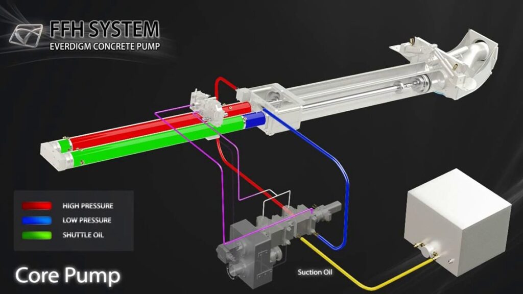
FFH CLOSED-CIRCUIT HYDRAULIC SYSTEM (FREE FLOW HYDRAULIC) HYDRAULIC OIL TANK => MAIN PUMP => CYLINDER => MAIN PUMP
This is the hydraulic cycle applied to the boom pumping system of Everdigm concrete pump trucks. The hydraulic oil directly returns from the cylinder to the main pump, with only a small amount of hydraulic oil extracted to return to the oil tank for cooling.
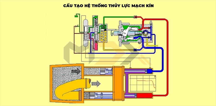
This generates optimal efficiency compared to systems where the entire hydraulic oil flow returns to the oil tank. This minimizes pressure loss and increases the working efficiency of the concrete pump truck, saving fuel.
OPEN-CIRCUIT HYDRAULIC SYSTEM HYDRAULIC OIL TANK => MAIN PUMP => CYLINDER => HYDRAULIC OIL TANK
This is the open-circuit hydraulic pumping cycle used by some other boom concrete pump truck manufacturers.
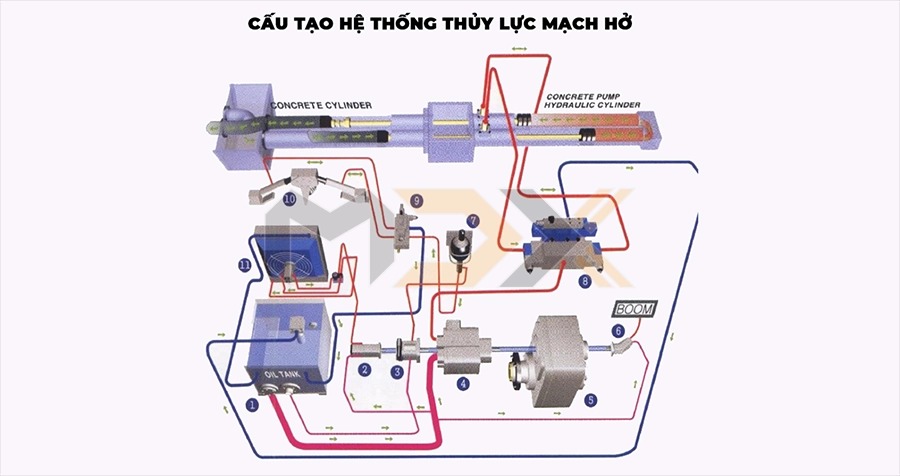
After being pumped to the cylinder, the hydraulic oil completely returns to the oil tank. This causes a significant reduction, or even loss, of hydraulic oil pressure. Therefore, the main pump must operate at high power to ensure sufficient pressure for the pumping system, leading to higher fuel consumption and unstable pumping efficiency.
All Hyundai Everdigm concrete pumps in Vietnam utilize the modern FFH closed-circuit hydraulic pump system. Everdigm’s pumping equipment delivers excellent working efficiency and long pump lifespan. Below is a comparison table to help us understand Everdigm’s superior advantages over other pump brands regarding hydraulic pump systems:
| SYSTEM | CLOSED CIRCUIT | OPEN CIRCUIT | HIGHLIGHT |
Hydraulic System |
– No controller needed between pump and cylinder – Compact structure, minimizes noise and heat when opening or closing high hydraulic oil pressure, and also limits excessive pressure fluctuations and reduces component wear. | – Complex structure due to an additional controller between the pump and cylinder. – High noise and impact lead to rapid reduction in wear resistance. | Free oil flow |
| – Minimizes pressure loss and increases efficiency. | – The controller between the pump and valve obstructs the oil flow, resulting in low working efficiency of the oil in the system. | Efficiency | |
| – Small capacity oil tank, low hydraulic oil cost. | – Requires a relatively large capacity oil tank, high hydraulic oil cost. | Hydraulic oil tank capacity | |
| – Two sequential pumping lines minimize pressure fluctuations and impacts in the system. – The circulation cycle ensures a smooth and consistent concrete output. | – A single pumping line causes the sequential valve to always experience maximum pressure, leading to shorter valve lifespan. – Long cycles result in splattering concrete output. | Main pump | |
| – Low impact when pressure decreases on the pump control valve extends pump lifespan. | – The power used to control the concrete output is always under very heavy load, which can cause many unexpected failures. | Lifespan | |
| Most control components in FFH are enclosed and easy to repair. | – Continuous high-pressure operation reduces the physical properties of hydraulic oil. High oil costs. Complex structure makes repairs difficult. | Maintenance and Repair | |
| – Very short concrete pumping time. | – Relatively long concrete pumping time due to complex structure. | Concrete Output |
– Hawe (Germany) boom pump control valve block.
– Equipped with a vehicle cleaning water pump system.
– Robust, durable chrome-plated cylinders.
– Pump pipe holder on the rear outrigger beam.
– Automatic and manual greasing system for the hopper.
– Anti-drop valve for outriggers.
– HBC (Germany) wireless remote control.
– Aluminum alloy deck (anti-slip).
– Work lights mounted on the slewing platform.
COMMON HYDRAULIC SYSTEM FAILURES AND SOLUTIONS
Hydraulic pump systems significantly enhance the working efficiency of heavy machinery, especially closed-circuit hydraulic pumps. However, if not properly maintained, they are prone to damage, machine harm, and reduced operational lifespan. Below are some common hydraulic system failures and their solutions.
| Cause | – Dirt ingress into the suction filter. – Loose connection between suction hose and suction filter. – Pump operating beyond permissible speed. – Pump wear due to long-term operation. – Hydraulic oil temperature too high. | – Air ingress: Air can enter the pump through holes in connectors or hoses. – Incorrect pump selection: The installed pump may not match the system’s required speed or size. – Faulty coupling: The coupling between the motor and pump may be worn or loosely installed. | – Damaged directional control valve. – Insufficient supply pressure. – Damaged cylinder. | – Hydraulic oil temperature too high due to a faulty cooler. |
| Effect | – Pump produces excessive noise or vibration. | – Low or unstable pump output pressure. | – Hydraulic cylinder not operating, moving slowly, vibrating, or unstable. | – Oil tank too small: Tank capacity is insufficient to hold the hydraulic oil required for system operation. – Oil level too low: Insufficient oil in the tank for lubrication and cooling of components. – Using non-standard oil: Using oil that does not meet the hydraulic system’s requirements. – Damaged oil cooler: The oil cooling component is not operating effectively, preventing adequate oil cooling. – Relief valve continuously operating: When the system is not operating, oil from the pump continuously flows through the relief valve back to the tank, causing energy waste and heat generation. |
| Solution | – Clean the pump. – Check pump specifications. – Check and tighten valves. – Add lubricating oil when necessary. | – Replace all worn or damaged seals. – Inspect, repair, or replace pipelines if necessary. – Ensure pump and motor are compatible in terms of speed and power. | – Check the electrical system, including connection wires, fuses, switches, and related components. Ensure connections are secure and free from corrosion. – Thoroughly inspect the hydraulic cylinder, including the cylinder rod and cylinder barrel. Pay attention to signs of warping, scratches, or surface damage. Such damage can wear out piston seals and cause oil leaks. | – Verify that the hydraulic oil tank size is appropriate for the pump flow rate. The ideal tank capacity should be three times the pump flow rate. – Inspect and clean the hydraulic oil filter. If the filter is clogged or damaged, replace it with a new one. |

03-2026

03-2026
06/03/2026

12-2025

12-2025

11-2025